Thermal control system
Vacuum pumping system
Design features
Dimensions and cost of reduced pressure chambers
| Model | Useful volume, l | Dimensions of useful volume (W×H×D), mm | Temperature range,⁰С for chambers with thermal plate | Vacuum flange | Time to reach mode, min | Max. consumption current, A | Accuracy of temperature maintenance for chambers with thermal plates, ⁰С | Pressure, mmHg | Power supply parameters |
| ТS 150 | 150 | 500×500×600 | ..-70..+200 | ISO 160 | no more 120 | 16 | ±2 | 1х10-7 | 3L+N+PE, 380V/50Hz |
| ТS 500 | 500 | 800×800×800 | 20 | ||||||
| ТS 800 | 800 | 900×900×1000 | 24 | ||||||
| ТS 1000 | 1000 | 1000×1000×1000 | 26 |
Camera control system
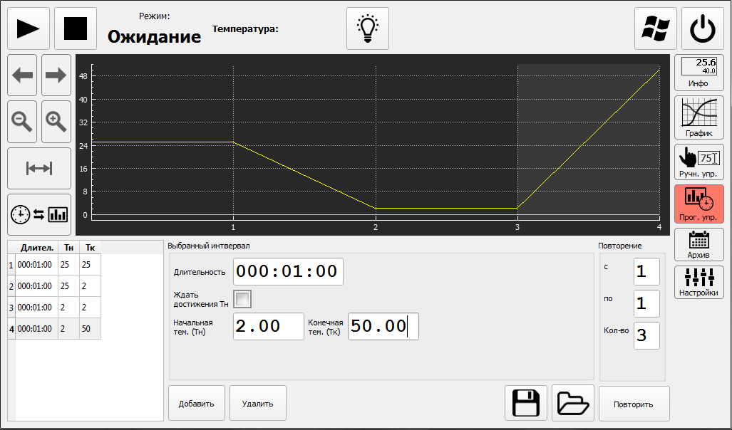
The camera is controlled using a Russian-language controller with a color display. Allows easy data entry and control. Easy to operate, very simple programming and tracking of test parameters. The LCD display allows, for example, entire graph segments to be highlighted and enlarged separately.
Main features: Russian-language and intuitive interface; Ethernet port for connecting to a computer; Sensor calibration via touch panel; Display of operating parameters for ease of service; Resolution: 0.1ºС, 0.1%; Setting the temperature setpoint in manual mode indicating the speed of reaching the set value; Setting the temperature setpoint in automatic mode in the form of a sequence of program steps described in graphical form; Saving data to a USB drive;

The chamber control system is built on the principle of balanced regulation of temperature and relative humidity, continuously, in real time, controls the power of the cooler and heater, dehumidifier and humidifier of the working volume, as well as:
• ensures the camera operates in a constant and programmable mode, monitors the camera’s operation and displays its status in real time;
• displays on the display the operating status of the camera, a temperature graph and a relative humidity graph;
• has an Ethernet interface and software for the ability to integrate the camera into a local network and remotely control the operation of both one and several climate chambers from one manufacturer, as well as combining them into a single structure;
• monitors and displays emergency situations on the screen and displays them on the screen, accompanied by a sound signal;
• in the event of an emergency, stops the operation of the camera if it threatens the performance of equipment or personnel;
• in the event of an emergency, it gives a sound signal;
• the occurrence of emergency situations is recorded in the system memory indicating the date and time, and is available to personnel in viewing mode;
• has the ability to switch the screen to “sleep” mode after a user-specified time interval, the transition of the screen to “sleep” mode is reflected in the operating mode of the camera;
• has a delayed start function accurate to days, hours and minutes;
• has the function of archiving test processes with data recording into the memory of a paperless recorder of a cycle length of 20 days with a recording interval of 10 seconds;
• has the function of monitoring the temperature of the test product with the display of measured values on the display screen and recording of data in the computer memory.
• displays the current date and time.
The camera control system provides:
• temperature setting resolution: 0.1 ºС;
• relative humidity setting resolution: 0.1%;
• time setting resolution: 1.0 s;
